Shape Optimization using grid free solver and evolutionary algorithm
S.
M. Deshpande1, G. N. Shashi Kumar2, A. K.
Mahendra2
1 Engineering Mechanics Unit, Jawaharlal
Nehru Center for Advanced Scientific
Research, Jakkur, Bangalore 500064, INDIA. email:
smd@jncasr.ac.in
2
Machine Dynamics Division, BARC, Mumbai 400085, INDIA
Grid
free solvers are very attractive numerical methods of obtaining
solution of PDE of fluid dynamics. The kinetic grid free solver
called LSKUM (Least Square Kinetic Upwind Method) has been very
successfully applied to a large number of practical flow problems
[1], [2], [3] and [4]. LSKUM requires a cloud of points around a body
(airfoil, wing, flight vehicle etc.) and connectivity N(Po) for each
point Po in the cloud. The connectivity N(Po) is a set of neighbors
of Po and is generally obtained by connectivity preprocessor. The
cloud can be generated by using any method for example, structured
grid generator leads to a simple cloud of points, several overlapping
grids leads to a chimera cloud. The LSKUM operating on a cloud of
points is a very powerful tool of obtaining numerical solution of
inviscid [2] as well as viscous flows [4] for geometrically complex
configurations. Combining LSKUM with an evolutionary algorithm (such
as GA for example) is a very attractive possibility in aerodynamic
shape optimization. Sashi Kumar, Mahendra and Deshpande [5] were the
first to apply LSKUM to a shape optimization problem.
Salient
features of LSKUM combined with GA are:
The
computational domain around airfoil has two clouds. One is the
background cloud which could be a Cartesian grid or points obtained
from an elliptic PDE based grid generator. The other cloud called
inner cloud is a relatively high density cloud around the airfoil.
In the present test case it is obtained by elliptic PDE based
method. This inner cloud has a hole which lies completely inside the
airfoil.
Points
in the computational domain are flagged, separate flags for points
inside, points on the
airfoil and interior points. Ray tracing is used to
blank the points inside the aerofoil. Connectivity is generated for
all the points except for those which are blanked.
Points
on the airfoil act as control points during optimization. Only these
points are allowed to change as optimization proceeds.
The
given population of shapes contains a number of airfoil
configurations (chromosomes). The population is generated by
allowing the y-coordinate of body points within an allowed band. The
variation is around NACA 0012 airfoil. LSKUM – NS code is used to
compute viscous flow around each airfoil . Several CFD calls are
required during optimization.
A
suitably chosen objective function (OF) is taken as a fitness
function which is used for GA search and selection procedure. The
high fitness values are used to select shapes as parents to produce
off springs. For example parents are chosen based on Roulette wheel
method [6] where the probability of a parent of being chosen is
proportional to its fitness value.
Each
of these parents produce two off springs by cross over and a simple
one point cross over scheme is applied. The probability of crossover
is set at 50% and then mutation is applied to off spring. Mutation
is carried out by randomly selecting a gene (control point) and then
changing its coordinates by an arbitrary amount within a prescribed
band. A new population is thus produced.
The
technique of elitism is used. The best and the second best members
in each generation are assigned to the next generation without cross
over or mutation [7].
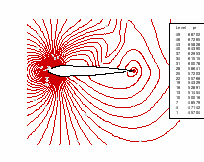
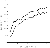
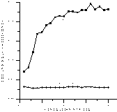
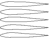
Figs
1, 2, 3, 4 show typical results where pressure contours for a shape
in one generation, variation of OF, variation of average lift and
drag coefficients with generation and best shape in each generation
(up to 20 generations) are shown.
|

|

|
|
Figure 1 Pressure contours for a typical airfoil
shape in the 1st generation
|
Figure 2 Variation of objective function (OF) with
generation
|
|

|
  Generations
|
|
Figure 3:Variation
of average lift and average drag coefficients with generation
|
Figure
4:Best shape in each generation
(1st,
5th, 10th,15th and 20th
generation)
|
References
[1] Ghosh A. K. and Deshpande S. M. “Least Squares
Kinetic Upwind Method for
Inviscid Compressible Flows” AIAA paper no
95-1735, 1995.
[2] Deshpande S. M. , Anandha narayanan K, Praveen C.
and Ramesh V. “Theory
and applications of 3D LSKUM based on entropy
variables” Intl J. for Numerical
methods in Fluids vol 40, pp 47-62, 2002.
[3] Ramesh V. and Deshpande S. M. “Least Squares
Kinetic Upwind Method on
moving grids for unsteady Euler Computations”
Computers and Fluids Journal,
vol 30/5, pp 621-641, may 2001.
[4] Mahendra A. K. “Application of Least Squares
Kinetic Upwind Method to
strongly rotating viscous flows” MSc thesis,
Dept. of Aerospace Engg, IISc,
Bangalore, Feb 2003.
[5] Shashi Kumar G. N., Mahendra A. K., Deshpande S. M.
“Optimization of airfoil shape using GA and grid free solver”
7th Aeronautical Society of India Intl Conference on CFD.
11-12 August 2004, Bangalore, India.
[6] David E. Goldberg “Genetic Algorithms in search,
optimization and machine learning” Addison – Wesley Publishing
Co. Inc, Reading, 1989.
[7]
B. Vanden Braembussche RA, Manna M. “Inverse design and
optimization methods” Lecture series 1997-05, Von Karman Institute
for Fluid Dynamics, Chausse de Waterloo 72, B-1640, Rhode Saint
Gevese, Belgium, Aprial 1997.


 Generations